

Key Takeaways
A careful transmission cooler installation starts with vehicle-specific information, not a guess about cooler size or hose routing. Take time to check fitment, protect the lines, and verify fluid level after the work.
- Confirm the cooler and fittings are compatible with the vehicle and its transmission circuit.
- Choose a location with airflow, safe clearances, and room for service.
- Route and secure lines away from heat, abrasion, and moving parts.
- Follow the manufacturer’s fluid-level procedure and check for leaks.
- Stop driving if fluid is escaping or the transmission behaves abnormally.
Understand cooler types and vehicle compatibility
A transmission cooler installation guide should begin with the vehicle’s existing cooling arrangement and the conditions it will face. Some vehicles use a cooler integrated into the radiator, while others have a separate heat exchanger or a factory bypass arrangement. Check the service information for the exact vehicle and transmission before deciding whether an auxiliary cooler is suitable.
Compare plate-and-fin and stacked-plate designs
Plate-and-fin coolers use rows of passages and fins to transfer heat to the air moving through them. Stacked-plate designs use layered plates to create fluid passages and are often compact for their cooling surface. The exact construction and capacity vary, so compare actual dimensions, connection types, and the manufacturer’s application information rather than judging by appearance alone.
For a concrete example of a vehicle-specific kit, the Mishimoto MMTC-F2D-08SL is described as a stacked-plate cooler designed for 2008–2010 Ford 6.4L Powerstroke trucks, with adjustable brackets. That information applies to that named application; it is not a fitment recommendation for other vehicles. A basic comparison can help narrow what to investigate, but it cannot replace the vehicle’s fitment instructions.
| Design | General construction | Practical consideration |
|---|---|---|
| Plate-and-fin | Passages and fins arranged in rows | Compare its size and specified capacity with available space |
| Stacked-plate | Layered plates form fluid passages | Check bracket positions and connection orientation |
| Factory integrated | Cooler incorporated into another component, often the radiator | Verify how the existing circuit is routed and controlled |
Use the table as a starting point, not as a ranking. The right choice depends on the vehicle’s circuit, available mounting area, and intended use.
Match cooler capacity to towing and driving conditions
Repeated towing, steep grades, heavy loads, and slow travel can place different demands on a transmission than ordinary commuting. Look for a cooler specified for the vehicle and expected use, and confirm that it will fit without restricting airflow to other components. A larger unit is not automatically a better choice if it cannot be mounted securely or connected as the vehicle maker directs.
The Mishimoto MMTC-F2D-99SL is described for 1999–2003 Ford 7.3L Powerstroke trucks and has a 37-row stacked-plate core. Its listed specifications are specific to that product and application. For a broader overview of fitting an auxiliary unit, this auxiliary cooler installation guide covers the basic planning and installation topic; still, use the instructions for the exact cooler and vehicle in front of you.
Check the factory cooler, thermostat, and bypass setup
Before adding parts, establish what the factory system already does. Some transmissions route fluid through a radiator cooler, a separate cooler, a thermostat, or a bypass valve, and the correct arrangement differs by vehicle. Use a repair manual or manufacturer instructions to identify which components must stay in the circuit and whether an auxiliary unit is permitted.
Gearbox terminology can help when you are reading service information, but labels alone do not identify the vehicle’s cooling layout. A guide to automatic gearbox types explains common transmission categories and branded names; use the vehicle identification and service documentation to confirm the installed unit. Electric portable coolers are a separate kind of equipment, so information about portable fridge power needs should not be confused with transmission-fluid cooling.
Gather tools, parts, and safety equipment
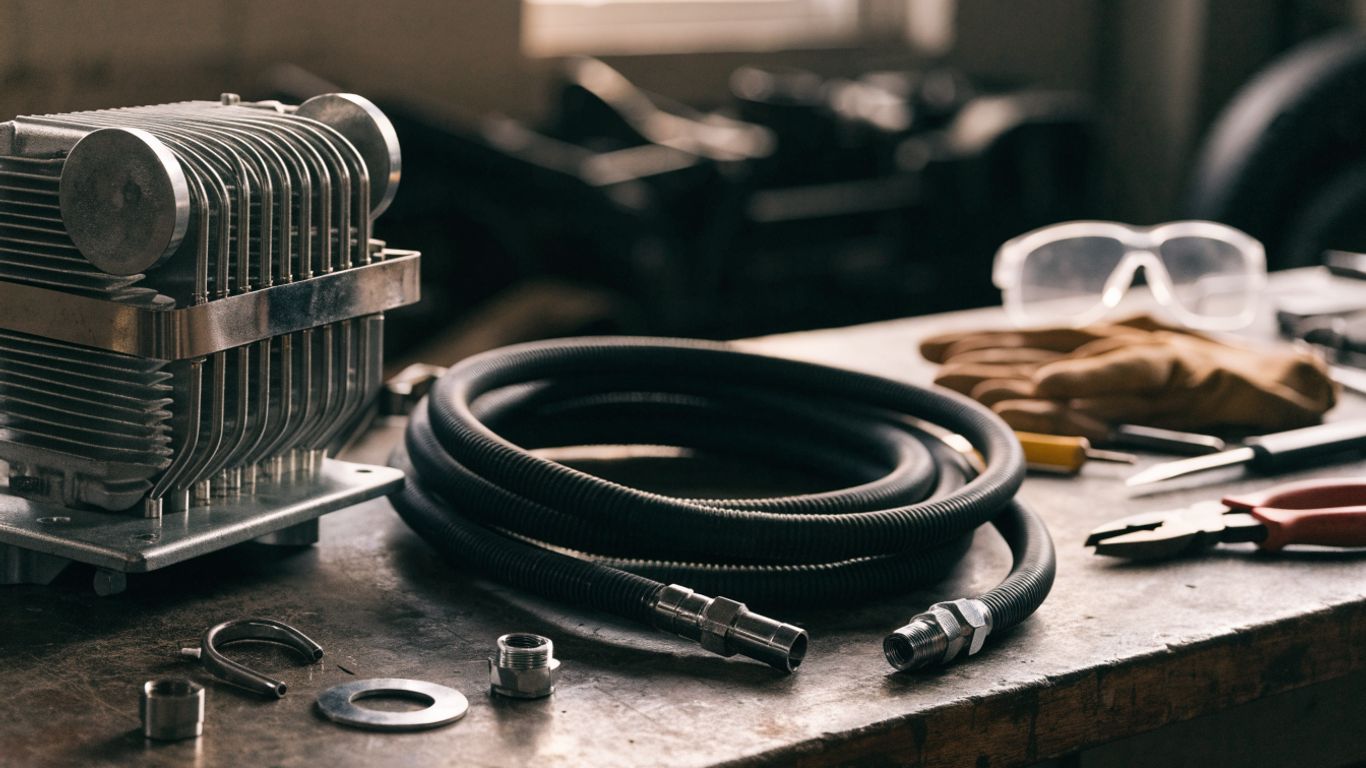
Good preparation reduces the chance of a rushed connection or a damaged line. Gather the cooler, vehicle-approved fittings, suitable hose, clamps or connectors specified for the application, the correct fluid, and the tools needed to remove and secure components. Keep the vehicle’s service procedure close at hand so fluid type, routing, and level checks are not left to guesswork.
Confirm fitting sizes, hose specifications, and fluid type
Fitting threads and hose diameters need to match the cooler and the transmission circuit; a connection that appears close is not necessarily compatible. Use hose intended for transmission-fluid service at the expected temperatures and pressure, and follow the cooler maker’s specification for clamps or reusable fittings. Confirm the required fluid type from vehicle documentation before opening the system.
A parts list is useful because small mismatches can halt the job after the vehicle is already apart. Before starting, check these items against the vehicle and cooler instructions:
- Cooler model and mounting hardware match the intended application.
- Hose and fittings match the specified sizes and fluid-service requirements.
- Fluid type and quantity are confirmed in the vehicle service information.
- Catch container, absorbent material, eye protection, and gloves are ready.
These checks do not replace the installation instructions, but they help reveal missing or incompatible parts while the vehicle is still intact.
Prepare the vehicle and protect nearby components
Park on a stable, level surface and give yourself space to work. Protect painted surfaces and nearby electrical connections from fluid, and keep a suitable drain pan beneath any connection that may be opened. Take photographs of the existing routing before removing anything; they can help distinguish original lines from the new cooler path during reassembly.
The idea of checking the substrate and conditions before beginning work appears in other kinds of installation planning too, such as preparing an indoor MUGA floor. The materials and procedures are entirely different, but the practical lesson is familiar: assess the starting condition and plan the work before committing to installation.
Let hot parts cool and support the vehicle securely
Transmission fluid, exhaust parts, and nearby engine components can remain hot after a drive. Allow them to cool, then use the vehicle’s specified lifting points and properly rated stands if access underneath is necessary; never rely on a jack alone. Keep hands, clothing, and tools clear of fans and other components that may move unexpectedly.
Choose a mounting location
A suitable mounting point needs airflow, firm support, and enough clearance for lines and nearby components. Look for an area allowed by the vehicle and cooler instructions, and consider whether the cooler can be inspected later without removing unrelated parts. The most convenient spot during installation may not be the best place once the vehicle is driven, serviced, or loaded.
Balance airflow, clearance, and service access
The cooler must receive airflow while remaining accessible for inspection and cleaning. Check that the proposed position leaves room for the hose bends and fittings, and that the core can be removed or examined if necessary. Where the cooler maker specifies a particular orientation or mounting position, follow that guidance rather than assuming every layout is equivalent.
Keep the cooler away from exhaust heat and moving parts
Heat from exhaust components can undermine the benefit of placing a separate cooler in the airflow, while vibration or contact with moving parts can damage its core or connections. Trace the nearby fan, belts, steering parts, and suspension through their full range of movement where practical. Leave enough room for the engine and body to move on their mounts without pulling on a line.
Avoid blocking the radiator or air-conditioning condenser
A cooler mounted in front of another heat exchanger can affect airflow to it. Check the vehicle’s packaging instructions and preserve the area needed by the radiator and air-conditioning condenser; do not cover a large portion of either core without explicit application guidance. For a temporary climate-control setup, heater placement also needs careful attention, as guidance on safe portable event heating illustrates in a different setting.
Mount the transmission cooler
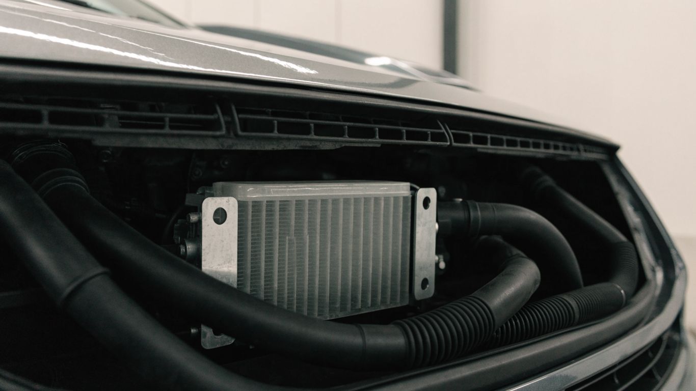
Once the location is chosen, mount the cooler so it stays secure over bumps and vibration without loading its fluid connections. Follow the kit instructions for brackets and fasteners, and avoid improvising a support that could flex or rub through the core. Take a moment to check clearances before tightening everything fully.
Use appropriate brackets and vibration-resistant hardware
Use brackets intended for the cooler or an approved vehicle-specific mounting kit. Fasteners should be suitable for the mounting surface and tightened as directed; overtightening can distort parts or strip threads. Avoid relying on a fragile nearby component as the sole support, and make sure the cooler cannot rock into the radiator, condenser, or bodywork.
Protect lines from heat, abrasion, and sharp edges
Route each line along a protected path, away from exhaust heat, sharp metal edges, and surfaces that could wear through the hose. Use suitable clips or protective sleeves where called for, leaving enough slack to accommodate movement without allowing the line to sag. Check every point where a line passes through or near a panel, bracket, or other component.
Check clearances around moving components
Before connecting the circuit, inspect the cooler and its brackets against nearby fans, belts, steering, and suspension components. The video placeholder below can help readers find a visual demonstration of a typical installation, but the vehicle-specific service procedure remains the authority for routing and fitment.
Recheck the clearances after the cooler is firmly mounted. A line that is safe while hanging loose can shift once filled or secured, so inspect the entire planned route before moving on.
Connect the cooler to the transmission circuit
Connections determine whether the cooler is part of the intended fluid path, so identify the correct lines before cutting or disconnecting anything. Vehicle designs vary, and the correct return line, flow direction, and place in the circuit must come from application-specific information. If the instructions do not clearly identify these details, pause and verify them rather than testing connections by trial and error.
Identify the correct return line and cooler flow direction
Use the repair information to identify the transmission cooler lines and the intended flow direction. Do not assume that line position or temperature alone is enough to establish which line is the return. Mark the lines before separating them, and confirm whether the auxiliary cooler belongs before or after an existing cooler as specified for that vehicle.
Follow the vehicle-specific routing instructions
Use the route shown in the vehicle and cooler instructions, maintaining a smooth path without tight bends, pinching, or unnecessary joints. If instructions specify the order of cooler components or a particular hose connection, follow that arrangement. A generic diagram may not account for differences in the radiator, transmission, or factory line fittings on a particular vehicle.
Preserve factory bypass functions and secure all connections
Do not remove, block, or bypass a thermostat or factory valve unless the vehicle-specific instructions explicitly direct it. Make sure fittings are fully seated and secured using the specified method, then check that hoses cannot pull loose or rub against surrounding parts. The purpose of the additional cooler is not to defeat a control feature that is part of the original circuit.
Refill and verify the system
Opening the cooler circuit can lower the fluid level, and the amount needed depends on the vehicle and the installation. Refill only with the specified fluid, then use the exact checking procedure for that transmission; some procedures depend on fluid temperature, engine state, or selector position. A level judged by a generic method can be misleading.
Check fluid level using the manufacturer’s procedure
Follow the vehicle maker’s steps in the stated order, including any temperature range or engine-running requirement. Add fluid gradually and recheck as directed rather than filling to an assumed capacity. If the transmission has no conventional dipstick, use the specified level-check point and procedure instead of relying on a visual guess.
Inspect for leaks at idle and after a short test drive
With the system reassembled and the vehicle on stable ground, start it according to the service instructions and inspect the connections for leaks. Keep clear of moving parts, and shut the engine off if fluid appears at a fitting or hose. If the initial inspection is clean, follow the manufacturer’s guidance for any brief road test and check again afterward.
Recheck fluid level, line temperatures, and mounting security
After the test, check the level again using the prescribed method and look over the cooler, brackets, and full length of each line. Temperature differences can offer context about circulation, but they are not a substitute for the manufacturer’s diagnostic procedure or a proper flow check. If the results are unclear, have the system assessed rather than interpreting a single temperature reading as proof of correct operation.
Troubleshoot common installation issues
Problems after installation often point to a connection, routing, or fluid-level issue, but transmission symptoms can have other causes as well. Start with a careful visual inspection and the vehicle’s troubleshooting information. Avoid driving further while fluid is leaking or the transmission is behaving abnormally.
Address leaks, kinked lines, or restricted flow
A damp fitting, loose clamp, crushed hose, or sharp bend deserves attention before the vehicle is used again. Shut the engine off before correcting a connection, and do not tighten fittings blindly if their seating method or torque specification is unknown. Replace damaged hose or fittings with the specified parts, then recheck fluid level using the proper procedure.
Investigate overheating or delayed shifting
If the transmission runs hot or shifts differently after installation, verify that the cooler circuit follows the correct routing and that the lines are not kinked or trapped. Confirm the cooler is receiving airflow and that the factory thermostat or bypass arrangement remains intact. Because these symptoms can also signal an underlying transmission fault, use vehicle-specific diagnostics or consult a qualified technician if a basic inspection does not reveal the cause.
Stop driving if fluid loss or abnormal transmission behavior occurs
Fluid loss can quickly become serious, and slipping, unexpected shifts, warning lights, or unusual noises should not be ignored. Stop in a safe place, switch off the engine, and arrange appropriate assistance rather than trying to drive far enough to see whether the symptoms pass. Once the fault is corrected, inspect the installation and verify the fluid level again before returning to normal use.
Conclusion
A dependable transmission cooler installation comes down to matching the cooler to the vehicle, mounting it securely, routing the lines as specified, and checking the system carefully afterward. When fitment, flow direction, or fluid-level instructions are uncertain, pause and consult the vehicle-specific documentation or a qualified technician rather than improvising.
Frequently Asked Questions
Do all vehicles need an auxiliary transmission cooler?
No. Whether one is appropriate depends on the vehicle’s factory cooling system, transmission, and intended use. Check the vehicle maker’s instructions before adding one.
Can I mount a transmission cooler in front of the radiator?
Some installations place a cooler in front of another heat exchanger, but space, airflow, and the vehicle’s instructions matter. Confirm that the position will not obstruct required airflow or create a clearance problem.
Which transmission line should connect to an auxiliary cooler?
The correct line and circuit position vary by vehicle. Identify them using the service information and cooler instructions rather than guessing from their location or temperature.
What type of hose should I use?
Use hose specified for transmission-fluid service and suitable for the application’s temperature and pressure. Confirm its dimensions and compatible fittings in the manufacturer’s instructions.
Does an auxiliary cooler replace the factory cooler?
Not necessarily. Many systems retain factory components, and some include a thermostat or bypass that must remain functional. Follow the vehicle-specific routing instructions.
How do I check the transmission fluid after installation?
Use the manufacturer’s procedure for the specific transmission. It may require a particular fluid temperature, engine state, or selector position, so a generic dipstick check may not apply.
What should I do if the transmission slips after installation?
Stop driving if it is safe to do so, then check for fluid loss and visible installation problems without approaching moving parts. Arrange professional diagnosis if the cause is not immediately clear or symptoms continue.